Distributor Cap Quality suggests it’s best to check your “as machined” New Distributor Cap and Rotor assembly to insure it will function properly and maintain your vintage car reliability. Vector files for this first installment of the information are:
DistributorCapRotorGapMeasurement (doc)
DistributorCapRotorGapMeasurement (pdf)
Content of the above files is as follows:
Distributor Cap Quality
Distributor Cap Quality provides info on verifying that your car’s vintage engine new Cap & Rotor (CR) combination (as factory machined) are good to use. Best to do the inspection since the manufacturer of each part didn’t mount the C/R on your distributor & verify the results meet specifications. Why? Ignition component life & engine starting/idling/running can be adversely impacted if CR restrict ignition excessively.
Theory:
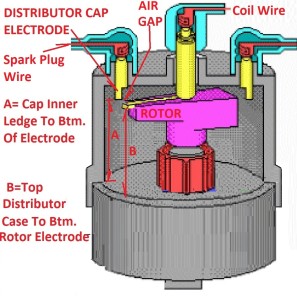
The CR direct the ignition coil output to the correct spark plug at the right time. The “connection” in the cap between the spinning rotor and the cap electrodes (for each spark plug wire) is actually an air gap which the coil power must bridge when the rotor points at the cap electrode as illustrated below:
Large Air Gaps causing high resistance force a coil to push harder = higher coil wire voltage.
Machining tolerances on the CR vary with current day manufacturers and can result in large variations in the gaps (especially within the same cap among each of the cap electrodes). Excessive gaps cause the ignition coil output voltage to surge higher than factory original values and result in early component breakdowns impacting engine performance. Inadequate gaps (too small) can cause interferences & component failures.
Excessive gaps or inadequate gaps can lead to reliability problems on your vintage car engine in a very short period of time.
Measuring Gap Indirectly:
The Total Physical Air Gap (TPAG) is the sum of three dimensions consisting of UP/DOWN, IN/OUT, and Angular Offsets which are not easy to see or measure with the CR installed.
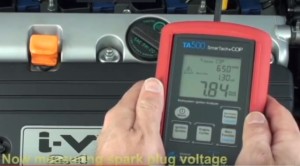
One quick way to indirectly measure for excessive TPAG is to measure the ignition coil wire (to distributor) voltage. Excessive TPAG between cap electrodes & rotor tip can cause voltages to soar. Typically coil wires have 3000 – 5000 Volts on stock vintage Mopar slant six engines (with good quality caps & rotors) but some current day CR excessive TPAG can cause voltages of 20,000 – 30,000 Volts (high volts accelerate cap center electrode, coil & ECM breakdowns).
Some equipment is made to measure these coil wire voltages without disturbing any part of the ignition system; the measuring “meter” slips around the coil wire & flashes the voltage:
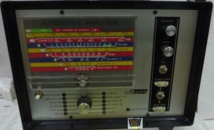
A less expensive approach (older test equipment) is an analog ignition analyzer such as the following including a Spark Output function which provides measurements up to 50,000 volts:
Grab a new CR and take a measurement; don’t be surprised that the CR TPAG is causing excess voltages with TPAG as high as .100” so corrections are likely required to improve reliability.
Taking a Physical Gap Measurement:
The above spark output/coil voltage measurements may indicate if the TPAG is excessive but do not indicate if it is too small. The analyzers don’t measure the TPAG only one of the results.
There is one Gap measurement you can take standing in the store with potential cap in hand; the UP/DOWN Gap. Look back at the illustration showing two dimensions A & B. Dimension A measures how far the cap electrode is from the shelf where the cap sits on the distributor and provides one part of the data needed to determine the UP/DOWN gap.
Measure Dimension B (distance the rotor tip is above the distributor “shelf”) which allows you to compare the A & B dimension. When dimension A is less than or equal to dimension B then there is “0” UP/DOWN gap which meets the desired condition or goal of 1960’s caps & rotors.
Conversely if Dimension A is greater than Dimension B there is a UP/DOWN Gap which is a reason to reject the CR combo. Current day cap Dimension A seem to range from 1 3/16 to 1 3/8 for Mopar slant six engines. Every cap electrode is checked for this A dimension and the largest A dimension measured is recorded. Rotor Dimension B tend to range from 1 ¼ to 1 5/16.
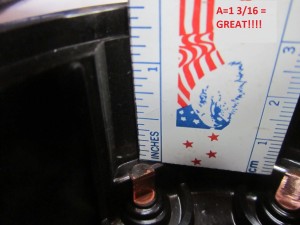
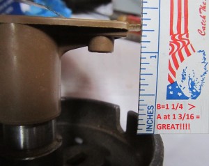
The following example shows an excellent & acceptable condition with the A dimension equal or slightly less than the B dimension. The UP/DOWN Gap is considered zero as desired.
Dimension A example is 1 3/16 from the electrode to the distributor cap shelf:
Dimension B is 1 ¼ from top of distributor casting to bottom of rotor tip:
Determining the remaining parts of the TPAG will be covered in Part 2.

