Improve Carter BB 1 Barrel Idle and Low Speed Operation by machining the Throttle Shaft Bearing areas to reduce vacuum leaks.
This file contains the step by step effort to that end:
CarterBBSThrottleShaftBearingRepairStepByStep (doc)
CarterBBSThrottleShaftBearingRepairStepByStep (pdf)
Content of the file is as follows:
Improve Carter BB 1 barrel idle and low speed operation
This information is similar to the Carter BBD 2 barrel idle information previously furnished:
http://www.plymouthcarclub.com/2015/07/carter-bbd-2-barrel/
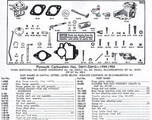
The attached images are for a Carter BB D6G1 (as used on 1942-48 Plymouth six) however most Carter BB are similar for this area of the carb as covered in this 49-54 Plymouth Carb parts diagram:
The parts discussed are the Body Flange Assembly I-628S including the 2-100 Throttle Valve and 3-449S Throttle Shaft and Arm Assembly.
Idle and low speed operation can be noticeably altered when the bushing areas of the Throttle Shaft & mating Body Flange Assembly become excessively worn and/or elongated. Air leaks past the worn areas (which is bypassing the Carb control areas). When substantial, it equates to a vacuum leak and the engine performs erratically.
If you have a lot of Throttle Shaft shaking going on, your carb (whether remanufactured or not) will need attention to this condition. This video describes excess clearances:
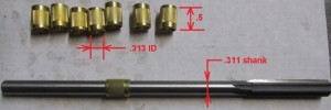
A reamer & bushing kit is available to repair the Body Flange worn areas. It is not marketed as a Carter BBS repair kit but it does the job with no problems. Carb Junky and Quadrajet sell such a kit marketed for Quadrajet & Holley 5/16” diameter Throttle Shaft repairs carbs. Kit looks similar to this:
The ½” long solid brass bushings fit one side of the Carter Throttle Body Flange perfectly and the remaining side (or end of the Throttle Shaft) needs the bushing filed off about 1/8” after installation.
The kit screws furnished are the incorrect size; 4-40 x 3/16” brass screws can be supplied from your local hardware store. At the same time you may want to pick up a #43 drill and 4-40 HS Tap so you can clean up the threads and/or repair any old screws that snap off when you are removing them from the Throttle Valve. Filling off any protruding Throttle Valve Retaining Screw ends before attempting to remove them might save you this time consuming step.
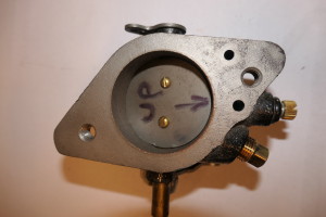
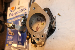
After removing the Throttle Body Flange from the carb mark the Throttle Valve with the “up” position and the direction facing the needle valve:
Remove the Throttle Valve Retaining Screws using a back and forth (counterclockwise to clockwise) method to try and avoid breaking off the low strength brass screws. Celebrate if you get out both screws without breakage otherwise you get the opportunity of drilling out the screw portion left in the bore and tapping with the 4-40 tap.
Remove Throttle Valve and Throttle Shaft and clean any corrosion off the flange wall. Good time to check the looseness of the shaft again so you have that reference to compare with the final end product of your efforts.
4LoosnessOfThrottleInOneBushing
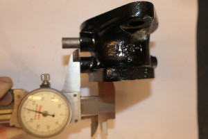
Measure each Throttle Body Bearing Area length:
These dimensions are used to determine where the reamer stop will be positioned to insure the brass bushing DOES NOT PENETRATE INTO THE THROTTLE VALVE AREA. Your goal is to insure the installed brass bushing goes in against a ledge. The ledge is the un-reamed portion of the bore left to act as a stop for the bushing.
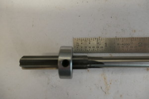
Set the stop (about 1/16” less than dimension) in position on the reamer:
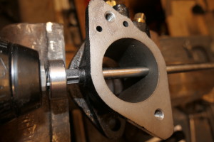
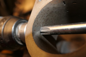
Mount the reamer on the drill so that you can exert a significant amount of pressure on the cut; it’s not normal for an aluminum flange to do it this way but you are reaming an iron casting (lube didn’t seem to help—made it worse):
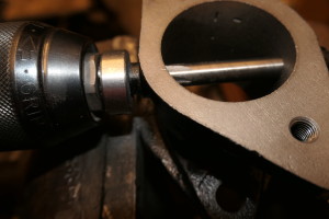
Machine until the reamer stop bottoms out on Throttle Flange bearing surface:
The reamer has the following appearance when the machining must end:
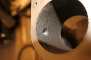
Once the reamer is removed a lip must be found on the inside of the bore:
The reamer is now used to do the other bore AFTER RESETTING THE REAMER STOP and installing the first brass bushing.
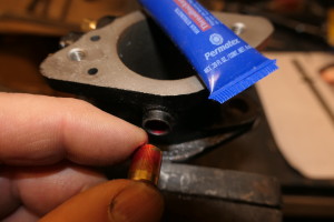
The first brass bushing can be installed using high strength Locktite to hold the brass bushing in place and also provide a seal:
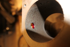
Remove excess Locktite promptly using the Throttle Shaft to push out the excess:
Re-examine the clearances now after both bushings are installed.
13ClearanceOfThrottleShaftInBushingIsReducedSubstantially
Make sure the Throttle Valve install is in the correct orientation and the lever on the Throttle Shaft points in the correct direction. Put both screws in first without Locktite, adjust (finetune location) the Throttle Valve, fully tighten one screw, remove one screw, then Locktite that one screw & install tightly, then remove the other screw for Locktite. These steps assure the Throttle Valve is in it’s final position before the screws are locked in position for a final time.
Once Throttle screws are installed with medium strength Locktite, removing them could be challenging if your Throttle Shaft and Throttle Valve positions are not correct the first time:
Do not use High Strength Locktite as it’s likely screw removal will end up in broken screw pieces in the Throttle Shaft when the screws break off.
Reassemble Carb.

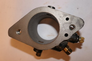
I am taking apart carter carbs that have already had throttle plaps changed, having no idea if they have been put in backwards? I cant see any real difference what way arouind they are fitted, please can you advise what happens if they get fitted backwards?
Suggest you think out of the box for the best solution. If the throttle plate is placed on the shaft and “fitted to the throttle body bore” then you can see how well the holes in the plate are aligned with the holes in the throttle shaft. A great alignment of holes to the other component would suggest that there is a good chance you have the setup for when to actually screw the throttle plate in place. Your mission is to get a great fit between the edges of the plate & the throttle bore so that daylight passing thru the gap is minimized. I expect that there is no written textbook method to solving the problem of not keeping track of the throttle plate position before disassembly but the approach of focusing on best fit-up between bore & plate by using the screw holes & throttle plate hole alignment is all you need to satisfy your concerns.